Color Color
- Summary Information about the Product: The SeaSonde®
- Where do you Set Up a SeaSonde?
- How Difficult Is It to Install a SeaSonde?
- How Is a SeaSonde Typically Operated?
- How Does HF Radar Measure Currents and Waves?
- What Other Options are there for Measuring Ocean Currents?
- Does It Operate from Oil Rigs or Drill Ships?
- Why Use a SeaSonde Rather Than a Conventional Phased Array?
- How Does the SeaSonde Measure Direction?
- Who Has Bought SeaSondes?
- What Are the Operating Costs?
Because the SeaSonde is compact and unobtrusive, it is normally installed at locations that do not require the round-the-clock security of the older large phased-array facilities. Hence, the sites are unmanned and data are transfered by dial-up modem or Internet to the desired user central location for display and archiving. In other words, the radar sites have no operating costs after installation except for electricity and phone bills.
- How Much Electrical Power Does a Single SeaSonde Take?
Less than 1 kilowatt.
- What Else Can It Measure besides Currents?
The most important descriptors of the open-ocean onshore wave field, i.e., heights, periods, and directions. In some cases, wind direction map estimates.
| Radar Spacing for Two-Site Network
- 15 - 40 km for long-range open-ocean mode SeaSonde Power Requirements -Radar and electronics: ~ 1 kw On the Coast Viewing the Open Ocean Where offshore and near shore currents and waves are of interest. Around the Mouths of Bays Where in and out-flow is critical. On Islands Straddling straits to the mainland. On Oil Platforms or Drill Ships For local surface current and wave field estimates; current mapping to ~60 km is also possible. See special section on offshore rig installation and operation. Cannot be used on a ship underway. |
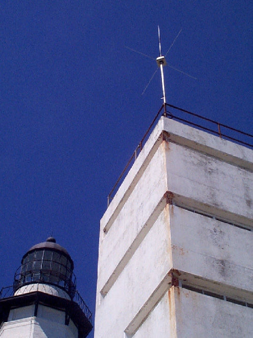
Transmit antenna at Montauk Point is located on a point of land that views south, east, and northeast. |
Offshore oil rigs like the floating semi-submersible shown here owned by Shell, often have need for SeaSonde or WaveSonde ocean surface measurements. The top of the derrick in the center became the location for the antenna in this case. |
Constraints on Coastal HF Radar Siting -Location should have good view of desired ocean coverage area, without obstruction from land or dunes - SeaSonde antennas are normally mounted on two 4-m posts out of reach -Antennas can be mounted on building roofs if necessary -Antennas must be within 150 m of mean water line. Cannot be back ~1 -even if located on high hill or mountain with good view of water at HF - Antennas must have no fences or obstructions in seaward direction -Tall buildings or trees behind antenna should be at least 50 m away -Cable runs from antennas to transmitter and receiver should not exceed 200 m -Transmitter, receiver, computer must be housed in environmentally controlled structure
|
How Difficult Is It to Install a SeaSonde?
•After Proper Preparation, Site Can Be Installed and Operating in ~2 Hours
-Complete hardware for a site fits in trunk of a car; two sites in a small van
- Preparations are outlined below
• Examine Alternative Locations in Area with Desired Ocean Coverage
- CODAR personnel will guide proper selection when sent maps and photos of candidate sites
- Ensure the site selected meets constraints outlined in previous section
- Lighthouses often have commanding views of desired coverage areas
| • Decide on Equipment Housing - Are there suitable buildings or houses available close to shore at candidate sites? -Often vacation homes can be rented/borrowed for non-permanent tests -- photo right is example of home in Virginia Beach that was used for 2- month SeaSonde tests during Fall 1997. - If not, plan to use 5-ft high metal weatherproof air-conditioned cabinet -The weatherproof boxes are commercially available -A wooden/metal shed should protect the metal weatherproof box and provide working space. these are commericially available, or can be built to order. -See sketch below for example of box/shed housing used by University of California at Santa Barbara for multiple SeaSonde stations. • Make Arrangements for Power & Phone Lines (if not in place already) • Select Specific Locations on Shore for the Transmit & Receive Antenna Posts |
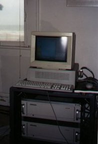 SeaSonde transmitter and receiver chasses in ruggedized field containers, as operated during COPE-3 at Virginia Beach, Fall 1997. Computer and monitor sit on top. A vacation beach house served as the base here. |
University of California at Santa Barbara oceanographers ordered fiberglass, airconditioned, weatherproof containers for their five semi-permanent SeaSonde deployments along the Santa Barbara Channel.The enclosure here is been located inside a home-made shed that offers both working space and additional protection along this rugged wind-swept coast. |
Why Are Phone-Lines Desirable if I Do Not Want Real-Time Data?
|
| After Installing It, Do I Need to Calibrate It to Ensure Proper Operation? Yes. The most critical part of any HF radar is the receive antenna and its pattern. If this is different from the assumed pattern, the bearing angles for the current and wave data will be misplaced, and sometimes there will be gaps in the coverage where the current vectors are missing. Our 25 years experience in this field has shown that ignoring this important step can sometimes lead to bad data and hence, a waste of time and resources. Why Would the Antenna Patterns Vary from the Expected 'Textbook' Ideal? |
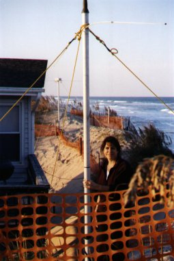 For the 2-month Virginia Beach COPE-3 deployment, the antenna posts were placed on the top of a sand dune ridge behind the house with the equipment. The posts can be equipped with nylon lines as shown here for such short periods. |
CODAR has designed a number of tools to make it straightforward and easy to calibrate and account for antenna differential errors.
•• The sea echo itself is used to measure differential effects among the three antenna channels. As the system begins operation and acquires data, the balance factors are stored in a diagnostics file,
•• CODAR has designed, sells, and recommends use of a small, battery operated transponder for calibration. This picks up the radar's signal, codes it, and retransmits it. This common signal through the three channels calibrates amplitude and phase mismatches as afunction of bearing, as the transponder is moved to different positions out in front of the antenna.
•• Patterns for calibration can be measured in this manner with the transponder in two ways:
-- If there is sufficient land seaward of the antenna (more than 40m), the pattern can be measured by moving to bearings every 5° and operating the radar in the 'pattern calibrate mode'. This takes ~2 hours.
-- If the antenna had to be placed at a cliff edge so that land patterns are not possible, boat patterns can be measured, with the boat at ~1 km and stopping every 5°. With planning, this can be completed in 2-3 hours. A small boat measuring patterns is shown in one of the photos.
•• Sea-echo and transponder calibration estimates are then compared, and suitable corrections are set in software. Done once, patterns rarely change and the system can be operated for years with nofurther attention to patterns unless the antenna position is changed or a new antenna configuration deployed.
How Is a SeaSonde Typically Operated?
Typical Configuration Is a Two-Station Pair
- Each site measures the radial component of a total 2-D surface vector
- Data from the two sites are combined on third-station computer at user facility
- Both sites operate continuously, independent of other, tuned to different frequencies
- Data can be transferred to central facility on any user-selectable schedule
- Total vector maps available at central station within minutes of acquisition
- Data can be stored on remote computers (up to 1 year of final
- current data) for transfer by disk and combining to total vectors at
- user convenience
Would I Ever Want to Use One Station Only?
- Stanford demonstrated utility of total vector maps from single-station SeaSonde over 3 year period
- Time and space resolution is sacrificed; short-term effects (e.g., tidal currents) may be lost
- From an oil platform or isolated island this may be the only option
What about More Than Two Stations?
- Continuous coverage can be extended along coast by adding sites
- Complex coastal regions are better covered by three or more (e.g., Monterey Bay)
- Can eliminate instability in producing total vectors along a baseline region joining just two sites (see Monterey Bay example)
- More than two networked SeaSonde sites are deployed in
- CODAR provides software for integrating multiple sites with arbitrary overlapping coverage
How Can Data Be Transferred from Remote Radar Sites to Central Station?
- Dial-up modem phone lines or Internet connections that:
- -- Can bring data back automatically on programmed schedule
-- Can transfer data at user log-on and request
- -- Can bring data back automatically on programmed schedule
- Recommended frequent log-on & data transfer to ensure proper operation
- 'Timbuktu®' available to emulate completely remote-site computer control
- CODAR provides data transfer software
What Safeguards Are Provided to Ensure Continued Operation of Unmanned Site?
- After power failures, system automatically restarts and continues its data acquisition schedule
- Hardware device detects hung computer and restarts system immediately
- Computer is automatically restarted once a day to clear anomalous conditions
- Remote operator can terminate operation and restart by modem control
How Often Does the SeaSonde Acquire New Data Samples?
- All systems in a network operate continuously, constantly acquiring and processing their data
- Typically, these data are averaged over one hour to reduce the noisiness of the sea echo, and a set of final radial map data is written to a file every hour; hence update maps are available every hour on this schedule
- This schedule can be changed per user needs to averaging/writing every half hour, for example, or every 20 minutes
- We recommend that no shorter time than 20 minutes be employed because:
- -- Currents typically do not change in shorter times than this
-- Current data may become too noisy over shorter intervals
- -- Currents typically do not change in shorter times than this
- Changes in data scheduling such as this can be made anytime with software provided, even over the modem at a distance
Am I Always Stuck with a Given Area Resolution, e.g., 3 km?
- No, this is user selectable, from 300 m to >3 km
- If one shortens the range resolution too small needlessly, this reduces the echo strength (which for any radar varies with the area in the radar cell) and hence, the maximum coverage distance
Changes in range cell size come by selecting the SeaSonde signal format, which is done with software provided, even over the modem at a distance
How Does HF Radar and the SeaSonde Measure Currents and Waves?
The Radar Coordinate System
- Every radar locates its echoes in polar coordinates: distance from the radar and angular bearing
- For current mapping the quantity extracted from the sea echo ateach range and bearing is the radial velocity which is: the projection of the total surface velocity along the directiontoward/away from the radar
How Range or Distance from the Radar to the Target Is Measured
- Every radar determines range from the delay of the target echo from the time when the signal was transmitted
- The SeaSonde does this based on a uniquely modulated swept frequency waveform that relates time delay between echo and transmit signal to the frequency at the receiver output
- The range cell size is therefore easily changed by varying thefrequency sweep of the radar signal
How the Bearing Angle to the Target Is Measured
- Conventional radar measures target bearing by forming a beam and scanning it across the coverage area
- Conventional radar antennas that will do this at HF are huge (e.g.,100 m long), a reason theSeaSonde was invented to overcome this impracticality
- The SeaSonde therefore uses three compact receive antennas with uniquely different angular patterns, and employs direction finding principles to get the target bearing; this is explained further in a subsequent section
How the Ocean Surface Radial Velocity Is Determined
- The surface current speed is determined from the Doppler principle
- Under this highly accurate relationship, the target speed toward or away from the radar is measured as a shift in the echo frequency from that transmitted
- This radial speed is calculated by the on-site acquisition and processing software
How the Radar Separates Current Speed from Wave Motions
- The interaction process responsible for the sea scatter is the Braggeffect
- According to this well-established principle, only ocean waves exactly half the radar wavelength moving toward and away from the radar produce significant scatter, to lowest order
- Waves of this known length have precisely known speeds
- Therefore, this known wave speed is subtracted from the total speed measured by the radar, and the difference is due to the currents
How the Radar Measures Wave Parameters
- In addition to the strong echo used for currents discussed above, a weaker but usable echo at displaced Doppler frequencies is seen in the echo
- These displaced Doppler echoes are sidebands due to the rotation of shorter Bragg-scattering waves as they ride on top of the underlying longer waves
- Hence the strengths and shapes of these echo sidebands are used to extract wave or sea state information
Drifters
- These float on the surface and are tracked (usually by satellite) until they are lost
- One or two drifters gives limited information about surface currentpatterns
- They are limited both in temporal and and in spatial coverage
- It takes many simultaneous drifters to get a good picture of surfacecurrents in an area of interest, which is an impractical and costly proposition
ADCPs (Acoustic Doppler Current Profilers)
- Mounted on the bottom, these measure the current velocity along avertical column up to ~2 m from the surface
- These are therefore a complementary remote-sensing technology tothe SeaSonde: one observes currents in a vertical column and the other maps currents over a horizontal surface area
Moored Current Meters
- They measure current at one point only
- The closest to the surface they can reliably be moored is ~6 m
- Currents at 6 m are often quite different than surface currents
- Surface currents have broader impacts on maritime activities and operations
- Current meter moorings are often lost or fouled
Satellite Altimetry (e.g., TOPEX)
- Altimeters from space can construct a pattern of the part of the flow due to earth rotation from sea surface height measurements
- Such patterns require passes over several days to synthesize this flow pattern
- Geostrophic (earth-rotational) flow is one only of several components that comprise the surface current
Satellite Infrared Mapping (AVHRR)
- Such maps show surface temperature, which is related qualitatively to currents
- Hence they show where currents are changing, but not their magnitudes
- They only work during the daytime and when it's not cloudy
- Under these conditions, one or two passes a day may be available
Aircraft Interferometric SAR (Synthetic Aperture Radar)
- This requires flights with crossing paths over the area of interest
- Such flights are expensive, several thousand dollars per hour
- The technique is still somewhat experimental in nature
Phased-Array HF Coastal Radars (see subsequent section for further detail)
- •• This is the predecessor to the SeaSonde
- •• The first HF current measurements by CODAR staff used phased arrays
- •• The SeaSonde was developed to reduce the large antenna size,associated difficulty of coastal operations, higher initial costs,and higher operating costs of phased arrays
Redesign of CODAR Products to Ultra-Small Antenna Sizes for Offshore Platforms
- The quest for smaller antennas was spurred by the demand for current and wave measurements from offshore oil rigs: the older antenna alternatives (e.g., phased arrays) are impossible for this mission
- We operated earlier versions of our present systems during the mid-80s from offshore rigs in the North Sea and Gulf of Mexico to
evolve this application
The Offshore WaveSonde®
- The Offshore WaveSonde is a smaller, simpler lower-powered unit that gives local information near the rig.
- This unit provides the following information within 2 km of the rig:
- -- A total surface current vector
-- The important descriptors of the directional wavefield, including significant waveheight, dominant direction, period, and the energy spectrum
-- A surface wind direction as determined by scatter from the shortwaves
- -- A total surface current vector
The Offshore SeaSonde®
- The Offshore SeaSonde is a redesign of the coastal SeaSonde to operate from an oil rig or drill ship
- The separate transmit and receive antennas are combined into one unit
- Radial maps of surface currents are available out to ~60 km
- These can be interpreted in terms of total currents with reduced
- space and time resolution
Antenna Placement Requirements
- The antenna unit must be located on top of the derrick at the highest point of the rig, to have an unobstructed view in all directions
- Other antennas or instruments (e.g., anemometers) should be located at the same or lower height than the SeaSonde antenna
Present Offshore CODAR Operations
- There is one Offshore WaveSonde unit on Shell's "Auger" tension-leg deep-water platform in the Gulf of Mexico
- An Offshore WaveSonde has been delivered and is being installed by Diamond Offshore on British Petroleum's "Ocean Clipper" drill ship in the Gulf of Mexico
- A third Offshore WaveSonde has been delivered to Sparta Marine Instrumentation for installation on Atlantia's "Morpeth SeaStar" mini-tension-leg rig in the Gulf of Mexico
Why Use a SeaSonde Rather Than a Conventional Phased Array?
Isn't a Phased Array Easier to Understand?
- The phased array is like conventional radars in that it forms a beam and scans it in bearing
- To do this at HF, the receive antenna must be quite long, because its beamwidth depends on the wavelength divided by the antenna length
The beam scanning can be done electronically in software instead of by rotating the antenna mechanically, which is the principle behind phased arrays
- Original proof of concept experiments by CODAR personnel were done with phased arrays on San Clemente Island off California in the early '70s
What are the Downsides of a Phased Array?
- At 24 MHz the receive antenna alone must be 100 m long (a football field), with 6 antenna elements to form and scan a beam ~11° in bearing width
- The beam can be scanned only within a ±45° sector, and hence there are about 8 independent beam positions in this sector viewed
- This 100-m antenna must be arrayed in a line very near the water with no fences or obstacles in front of it
- Nearly all beachfront areas--especially at desirable sites with a good view--are public access, meaning permission for long-term siting is very difficult to obtain
- Since the 16 array elements sit in the sand, vandalism and security are issues, adding to the expense of even temporary operations
- These were recognized to be severe operational and cost constraints, leading to the development of the SeaSonde
Doesn't the Smaller SeaSonde Antenna Imply Less Accuracy or Another Penalty?
- Not necessarily; angle accuracies/resolutions of 5° have been demonstrated
- The bearing is determined for each Doppler-produced radial velocity by using the known patterns of three very small colocated antenna
elements in a single unit mounted on a post out of reach - The software process that extracts bearing angle is called "direction finding" or DF, a very old technique dating back to the
beginning of the century - The particular algorithm we use is called "MUSIC" and has found wide application in the geophysical community for seismic and
acoustic sensors
What Sorts of Bearing Errors Does One Face with Both Systems?
- The main error with both systems arises when the antenna patterns differ from ideal due to
- -- Differential phases and amplitudes through the antenna element channels that are unknown and not accounted for
-- Distortions of the antenna element patterns due to nearby obstacles or terrain features
-- Both types of errors are detected and corrected in the SeaSondesystem by methods discussed in the section on installation
- -- Differential phases and amplitudes through the antenna element channels that are unknown and not accounted for
- The main effects of these errors in a phased array is to diminish the bearing resolution, thereby lowering the current speed estimate at a given position
- The main evidence of these errors in the direction-finding SeaSonde is to produce angular gaps or weak areas in the radial current coverage
Simple Direction-Finding Example with Idealized Crossed-Loop Antenna Elements
- A typical scenario has a different current radial velocity coming from each separate bearing
- After spectral processing, each radial velocity shows up at a different Doppler frequency. This is like looking at different radio stations, each on a different frequency coming from a different bearing, and being able to tune to each one separately
- There are three voltages available at each Doppler frequency: two from the crossed loops (that have a sine and cosine dependence on the bearing) and the monopole (which is constant with bearing)
- Bearing at each radial velocity (or Doppler frequency) is then obtained by taking the arctangent of the voltages at the loops normalized by the monopole voltage
Direction-Finding with Non-Ideal Antenna Patterns
- The same methodology outlined above can be used with non-ideal patterns, if they are measured and known
- Instead of the sine, cosine, and constant functions of bearing used above to represent the ideal patterns, the actual measured patterns are employed in a look-up table in software to fit the measured voltages at each Doppler frequency
The "MUSIC" Direction Finding Algorithm Used with the SeaSonde
- The above idealized method cannot handle more complex current patterns that can have multiple bearings with the same radial speed
- The "MUSIC" algorithm (which stands for MUltiple SIgnal Classification) can tell how many bearings have the same radial speed
and find these bearings - It employs the actual measured patterns obtained using the SeaSonde transponder, if these differ significantly from the desired
ideal patterns - Radial speed maps vs bearing and range are produced in real time with MUSIC from SeaSonde data and averaged typically over one hour
- Presently radial speeds are computed on a bearing grid every 5° over the sea, and we believe this to be a meaningful attainable resolution
and accuracy - Recall that the 100-m long 16-element phased array antenna produces a beamwidth (and angular resolution) of ~10°
- Request special handouts for more details on SeaSonde direction finding
Who Has Bought SeaSondes (and other HF radars)?
SeaSondes & Offshore WaveSondes
- Seaconsult Marine Research, Vancouver, BC Canada, 1992 (2 units)
- NOAA Environmental Technology Laboratories, Boulder, CO 1993 (2 units)
- Stanford University Biology Dept, CA, 1993, (1 unit)
- Shell Oil Company, Offshore WaveSonde for Auger platform, 1993 (1 unit)
- Taiwan Naval Weather Center, 1994-1998 (7 units)
- U.S. Naval Postgraduate School, Monterey, CA, 1994 (1 unit)
- India's National Environmental Engineering Research Institute, 1996 (2 units)
- NOAA Environmental Technology Laboratories, Boulder, CO 1996 (2 units)
- Univ. of Cal. at Santa Cruz, CA (1 unit)
- Oregon State University, Corvallis, OR (3 units)
- Diamond Offshore, WaveSonde for Ocean Clipper drill ship, 1997 (1 unit)
- Univ. of Cal. at Santa Barbara, CA (2 units)
- Rutgers University, NJ, 1998 (2 units)
- Sparta Marine Instrumentation, WaveSonde for SeaStar platform, 1998 (1 unit)
* Purchases to mid 1998
Contact SeaSonde | SeaSonde News | SeaSonde Customer Support | SeaSonde Sites |